Tips for assembling the O2 (Objective2) Headphone Amplifier Kit
Multithreaded JavaScript has been published with O'Reilly!Today, my friend Daniel Elliott and I assembled our O2 Headphone Amplifier kit, which we ordered from Head ‘n' Hifi. It took us about six hours to build the whole thing, however, if you've soldered things before you could easily have it completed in three hours (this was my first time soldering to a PCB).
While building this thing, we struggled in a few areas, and wish we had known some things in advance. In this article I'll outline these things.
Part Identification
The most tedious and error prone part of the process was identifying which parts were which. The Bill of Materials tell you which generic parts go to which location on the PCB, however, there wasn't an easy way to tell which parts we had were which generic parts. Unfortunately, if you order the kit from anywhere other than Head ‘n' HiFi, the parts will likely be different, and this list will be useless.
- R1, R2: Red Yellow Black Black Brown
- R10, R11, R15, R18: Brown Silver Black Black Brown
- R6, R12, R13: Brown Red Red Black Yellow
- R3, R7, R19, R23: Red Brown Yellow Black Brown
- R9: Orange Orange Black Red Brown
- R14, R20: Brown Black Black Red Brown
- R16, R22: Brown Brown Black Green Brown
- R17, R21: Brown Brown Black Brown Brown
- R4, R5, R8, R24: Red Brown Black Gold Brown
- R25: Brown Yellow Black Green Brown
- C10, C15, C17, C18: Blue Cubes
- C16, C21: 223, 312, apparently it doesn't matter
- C11, C12, C19, C20: BC 221
- C13, C14: Square White Things
- C1: 105Z (single)
- C6, C7: 105Z (pair)
- C2, C3, C4, C5: 381GB
- C8, C9: B1129
- D1, D2, D5, D6: IN5818
- U6: 7912ACT
- U5: 7812ACT
- Q1: 1C25AA (smalles one)
- Q2: 1D33AA (black top one)
Solder Order
As a general rule, start by soldering smaller components first, then slowly add bigger ones. We did resistors, then small capacitors, IC risers, diodes, etc. If you do the big parts first, they may get in your way later.
Part Orientation
Whenever you're dealing with a resistor, the direction you solder it to the board doesn't matter. When dealing with the tiny capacitors, it doesn't matter either (this I didn't realize). The cylindrical capacitors and diodes need to be in a certain direction (the PCB has hints everywhere). The transistors need to be in a certain way, and on the PCB you'll see a thick line where the back of the transistor needs to line up with. The IC chip risers have a cutout which align with the board, and the circles on the IC chip corresponds to the cutouts.
Transistor Oxidation
This was a real pain. The four transistors (U5, U6, Q1, Q2) had very oxidized leads when they arrived. If you look close, they almost look like a white dull aluminum color. Soldering them was an absolute pain and takes a long time. Unless, that is, you scratch the heck out of the surface. Take some sand paper if you've got it, otherwise just drag the edge of a blade against the leads, and you'll see them become really shiny. Once you do that, they will be a LOT easier to work with.
Battery Connectors
Before you solder the battery connectors in, you should really attach a 9V battery to them first. By doing so, you can be sure that the leads will keep the battery flush against the board. My friend did this and I did not. At first I had two leads which were pointed in different directions, and I had to re-solder it. By the time I was done, both sets of batteries protrude from the board slightly, while my friends are flush against the board.
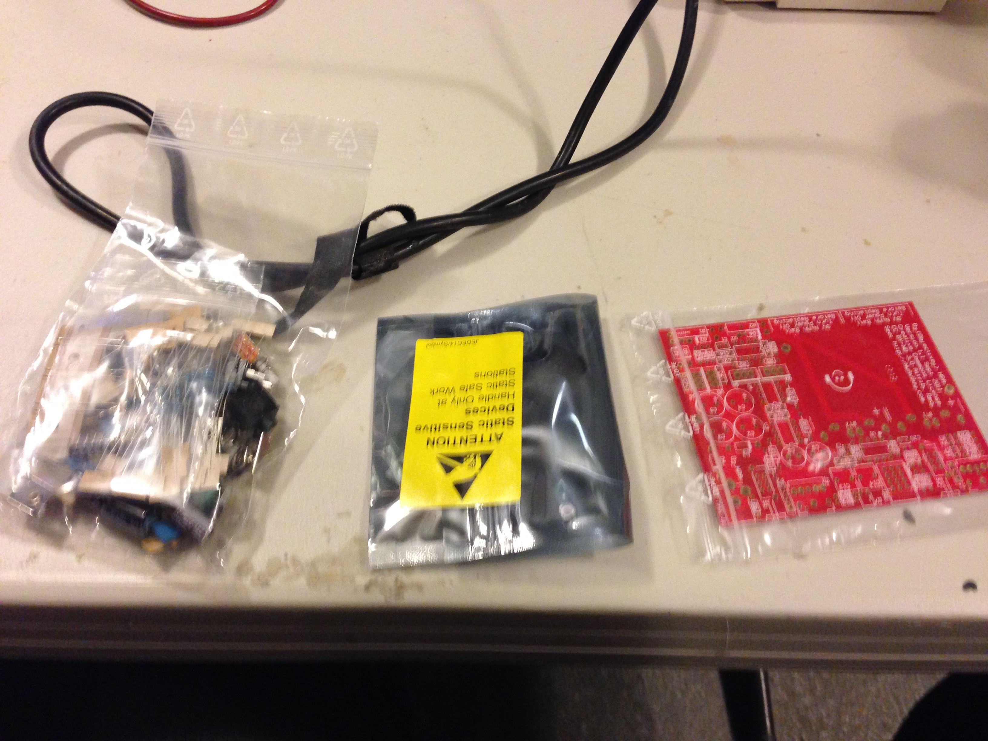
The Little Bag
When the parts arrive, you'll find inside a smaller bag containing some resistors and riser connectors. Don't open this bag; they are spare parts. Just throw it off to the side. If you do open the bag and mix it with your parts, it'll be harder to tell what goes where.
Power Precautions
Don't remove the batteries while the power is switched on. These are in the instructions. It may damage the circuit. Also, don't use a generic power source for the power jack. This thing is weird; it needs to use an AC -> AC power adapter. I didn't even know such a thing existed! They are normally AC -> DC.
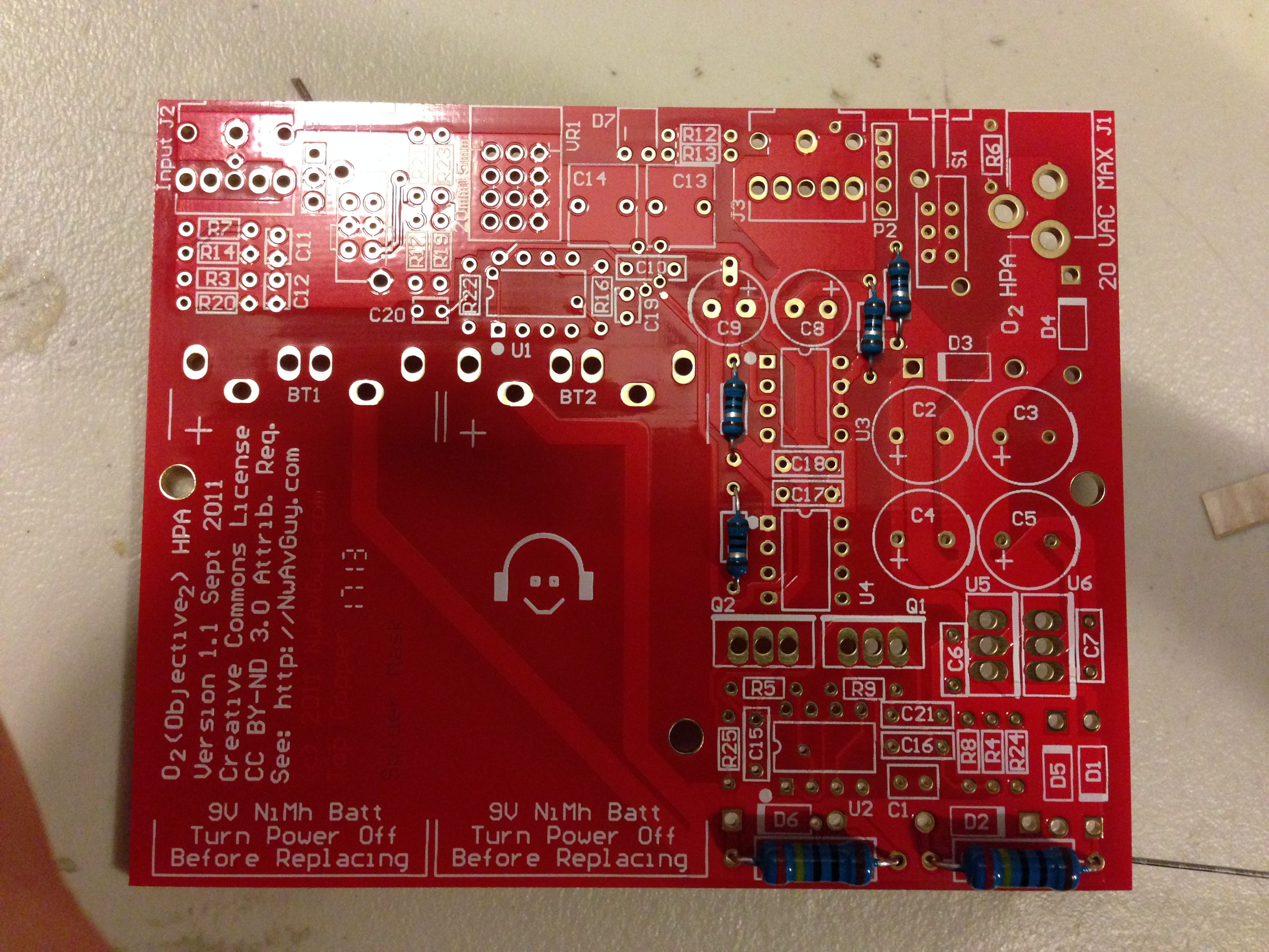
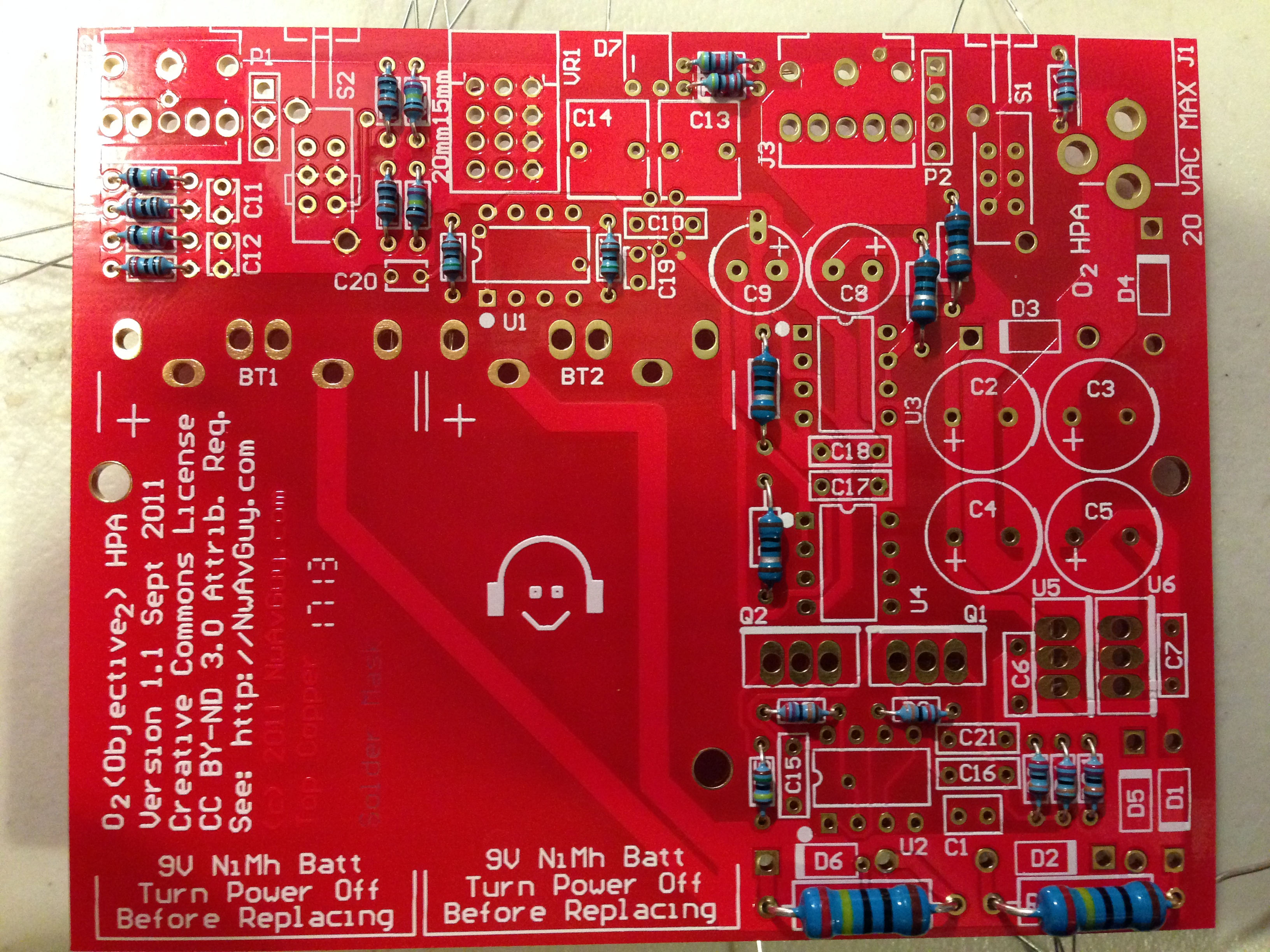
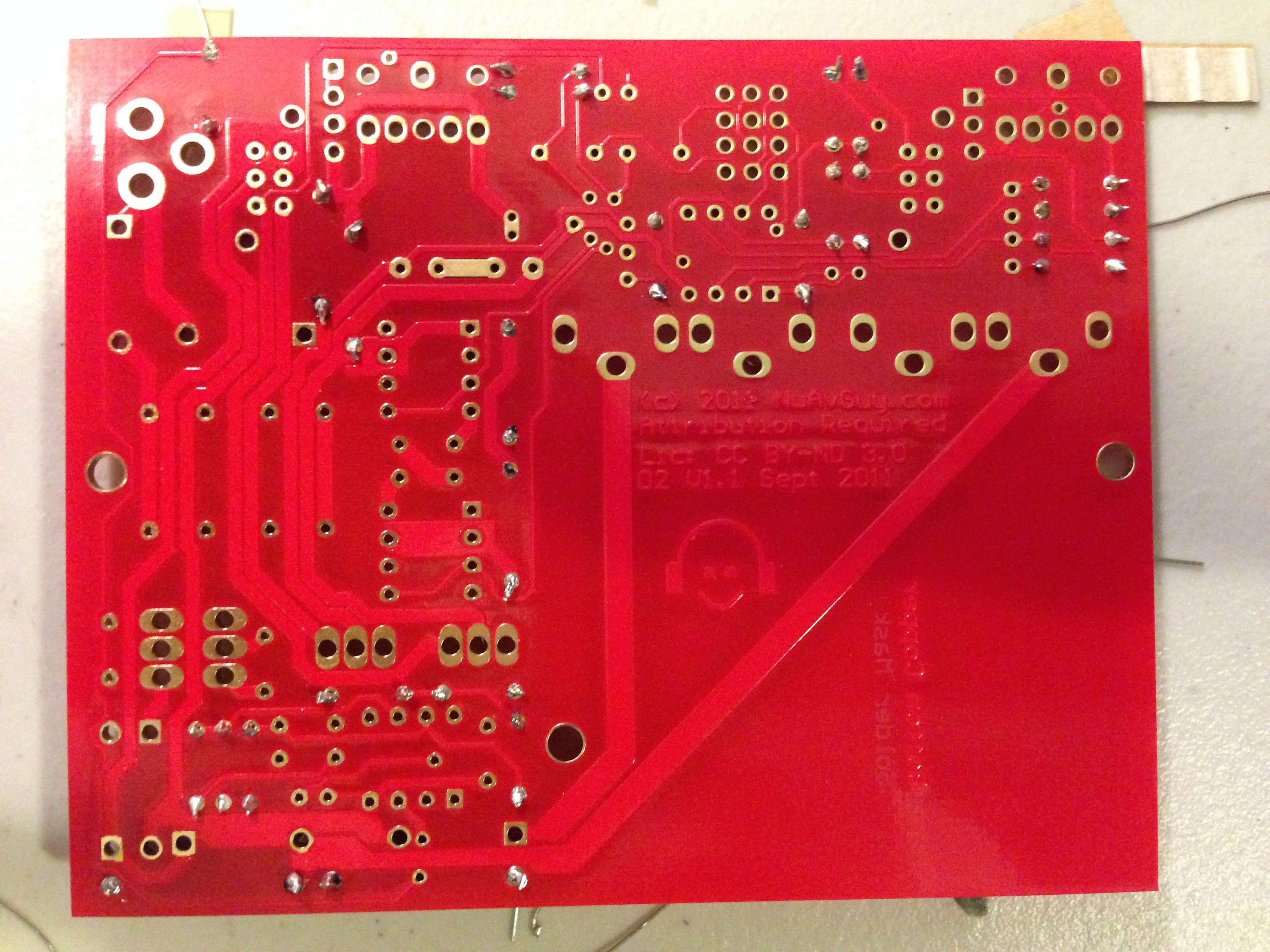
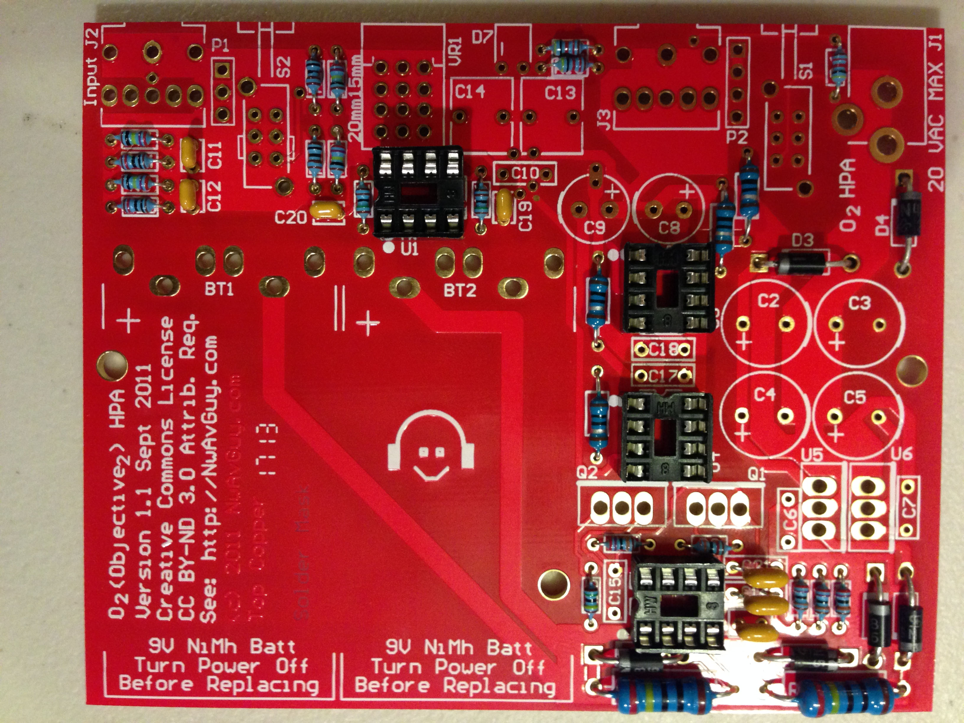
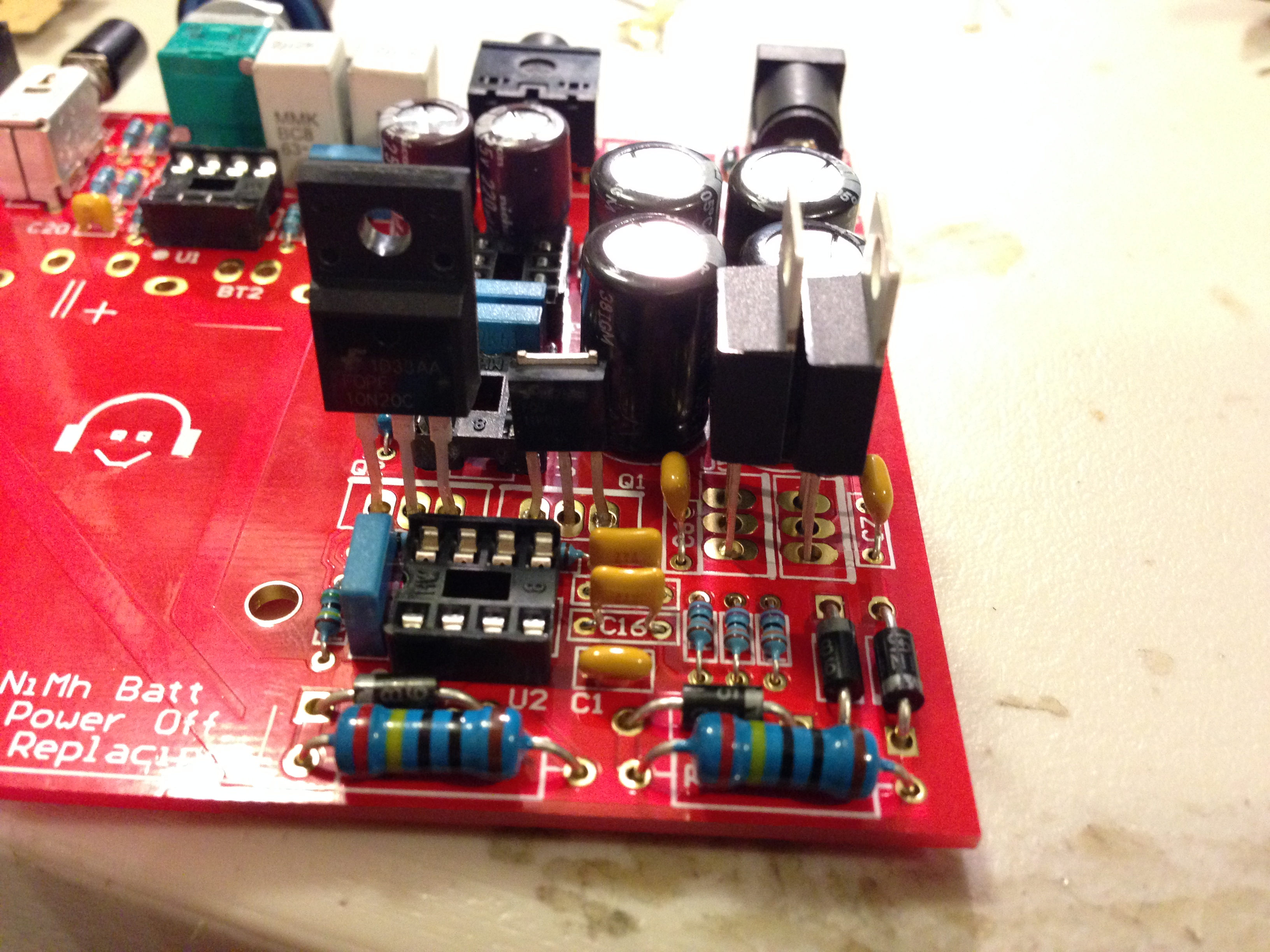
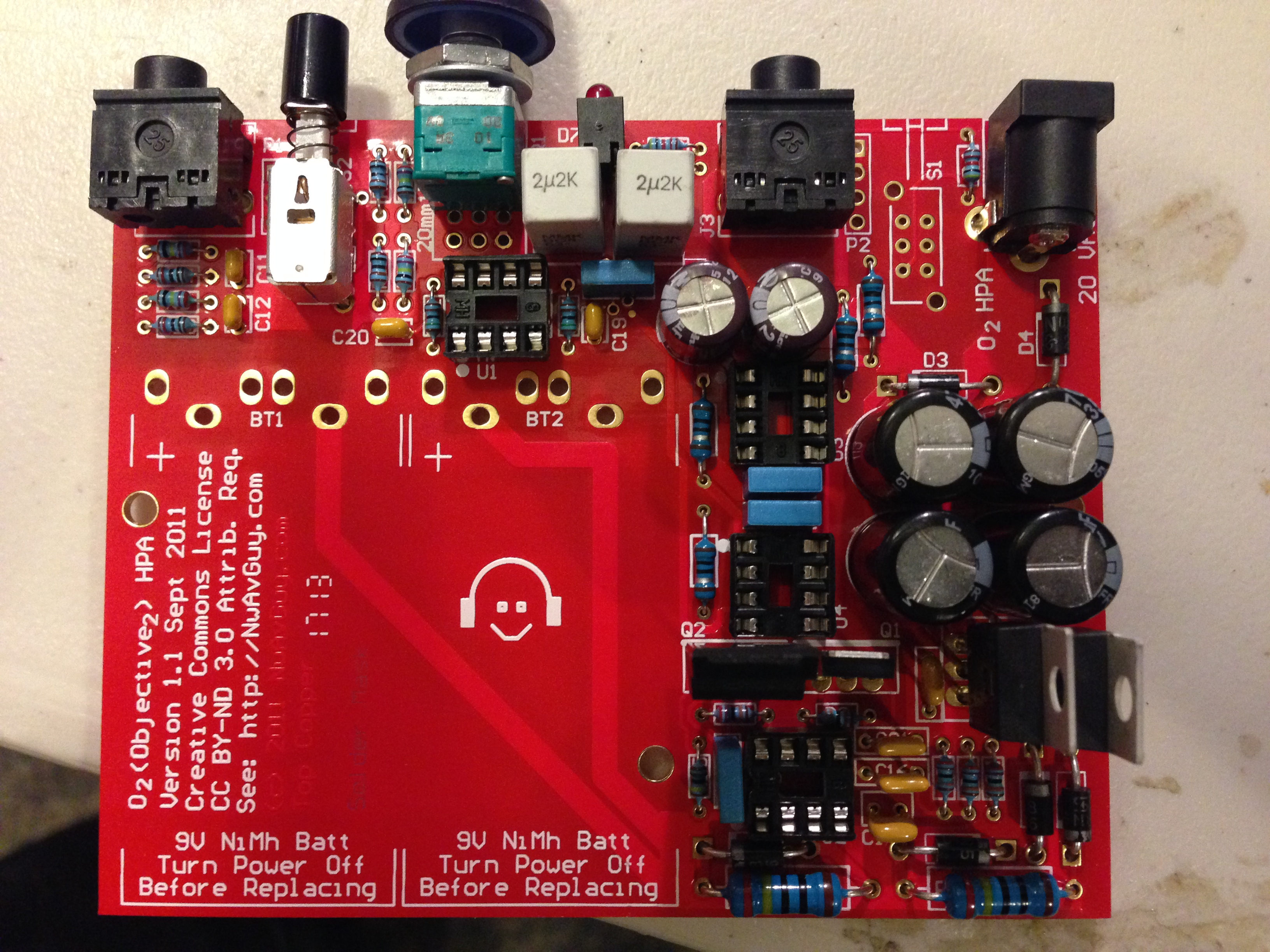
Pictures
Here's a bunch of pictures of the board throughout the process, because hey, following pictures is much easier than diagrams ;)
Thomas has contributed to dozens of enterprise Node.js services and has worked for a company dedicated to securing Node.js. He has spoken at several conferences on Node.js and JavaScript and is an O'Reilly published author.