PS2 RPI4 Part III: Underway
Support this website by purchasing prints of my photographs! Check them out here.Previously, in PS2 RPI4 Part II: Internals, I had disassembled the PlayStation 2 but hadn't made any irreversible changes. That is no longer true and the PS2 has begun its happy transformation into a modern general-purpose computing machine. A friend told me that the term for projects like this is “RestoMod,” a combination restoration and modification.
Optical Drive Door
To me, the most important part of this is that the front resembles a factory-made PS2. I'm happy to report that I mostly pulled that off. The first thing I did, after tearing apart the PS2, was to remove the door from the optical disc tray. There's a tiny latch that holds in in place and it was easy enough to separate.
Next, I placed a couple strips of electrical tape from top to bottom over the front hole in the case. Then I placed and replaced the door in the hole until it lined up perfectly. Once I was satisfied I used hot glue to hold it in place and then backed the hot glue with electrical tape so that LEDs inside the unit aren't visible.
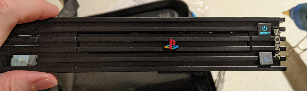
If you look closely you can see some light reflecting in the wavy surface of the hot glue. It can't be seen unless you look really closely, but it's there, and I hate it. I'll eventually try filling in the gap with black paint so that even when you're super close it'll look perfect, but for it's good enough.
Front USB Ports
I decided to keep the existing metal USB 2 enclosure instead of attempting to hack up some wires to be flush with the ports. This ensures the front of the unit resembles the original PS2 as much as possible. It also makes the ports sturdier than anything I could have glued together. It does mean I'm stuck with USB 2 ports, but I'll mostly be using mice, keyboards, and joysticks, which don't benefit from USB 3.
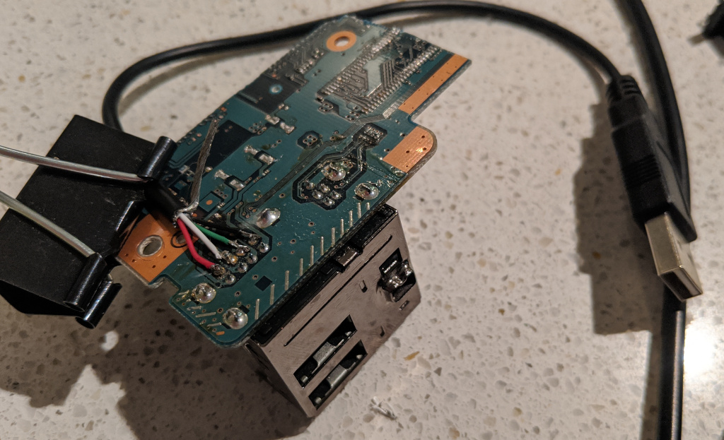
The USB enclosure is soldered to the motherboard, which I could have de-soldered, but the motherboard also has screw holes. This helps keep the hole alignment perfect. So, I hacked a chunk of the motherboard off. This was done by scoring the surface repeatedly with an exacto blade and then finally cracking it with a pair of pliers.
Once that was done I de-soldered every component from the motherboard to prevent any phantom current draw. Then I butchered two USB cables (actually, four, until I found decent ones) and soldered them to the USB pins. Here's an in progress photo of the first USB cable once it was attached:
Fan
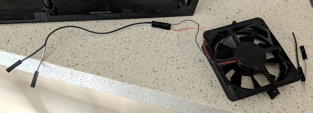
While technically not required, I wanted to reuse the existing fan to keep the case cool. I'm pretty sure the previous owner had replaced the fan as it was missing a screw and was installed backwards. The fan uses some of the tiniest wires I've ever seen as well as a tiny plug. I removed the plug and soldered a pair of jumper wires that'll attach to the Ground and 5V GPIO pins on the Raspberry Pi. As long as the Pi (and therefore the overall machine) is powered on, the fan will blow.
Power Supply and USB Hub
I wanted to keep the original power supply for a few reasons. First, the current that it supplies is pretty decent, being 12V at up to 5 Amps. Second, the incoming power cord plugs into it perfectly and it perfectly fits in the bottom of the case. Third, I wouldn't have had to spend an hour breaking open another power transformer to get it to fit in the case. Unfortunately there was no possible way to get an HDMI adapter to fit in the back of the case with the original power supply in tact.
I gutted a transformer that outputs 12V at up to 3 Amps. It has just barely enough vertical clearance to fit in the bottom of the case. This transformer feeds power to a USB 3 hub. The only place the hub could fit—without destroying any of the metal frame—is far off in stage left against the side of the case. I had to bend LEDs, put electrical tape on the frame for insulation, and turn the hub sideways for it to fit. The hub is currently held in place with thick metal wire.
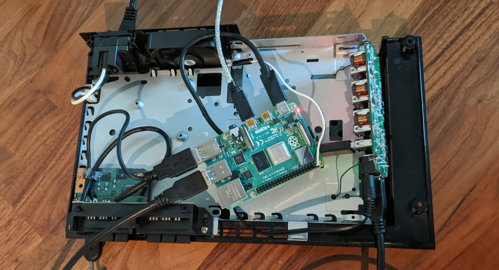
The Raspberry Pi is powered by the hub, and the hub is plugged into the Pi for data. Ideally, all USB devices will plug into the hub, but unfortunately the two USB cables for the front panel are too short. I'll just plug them into the Pi's USB 2 ports for now since they're only used for input devices.
Overall Progress
So far the project is going swimmingly. I did end up choosing to keep the frame which really helps make it feel sturdy. The amount of wires in the device is starting to get a little out of control—USB 3 Type B cables are huge!—but I'll soon zip-tie them into submission. Nine inches is the ideal cable length for this project, but everything seems to come as 3 feet.
I just received a 3.5mm audio jack in the mail that I'm going to try to put in the existing optical audio hole. I did de-solder the optical jack and could theoretically wire it up to work. It would be a cool engineering feat but I'd never use it anyway. I'll probably glue the audio jack to the bottom of the case, solder a 3.5mm male cable to it, and run it up to plug into the Pi.
The HDMI part might be the most painful part of the project. These cables have a ton of wires and are hard to bend. I took a short Micro HDMI to HDMI cable and stripped the rubber coating so it would bend easier. The female end is nice because it's black rubber and I was able to cut it down to fit the existing case hole. Too bad it's probably not long enough. Adafruit has a great collection of HDMI terminals (males, females, standard, mini, micro) that share a common flex wire. I'll probably end up buying that, though the case hole won't be a good fit.
I also have an Ethernet jack waiting for me. I might have to remove the legalese / serial number sticker to make room for the port. That isn't exactly ideal since the sticker is technically part of what makes the PS2 a PS2. I also might buy a USB wifi adapter and stick antennas out the back, which would also need to use the sticker area, so maybe it's inevitable. The expansion bay panel is a bit too wobbly to mount anything important to it.
Thomas has contributed to dozens of enterprise Node.js services and has worked for a company dedicated to securing Node.js. He has spoken at several conferences on Node.js and JavaScript and is an O'Reilly published author.